01
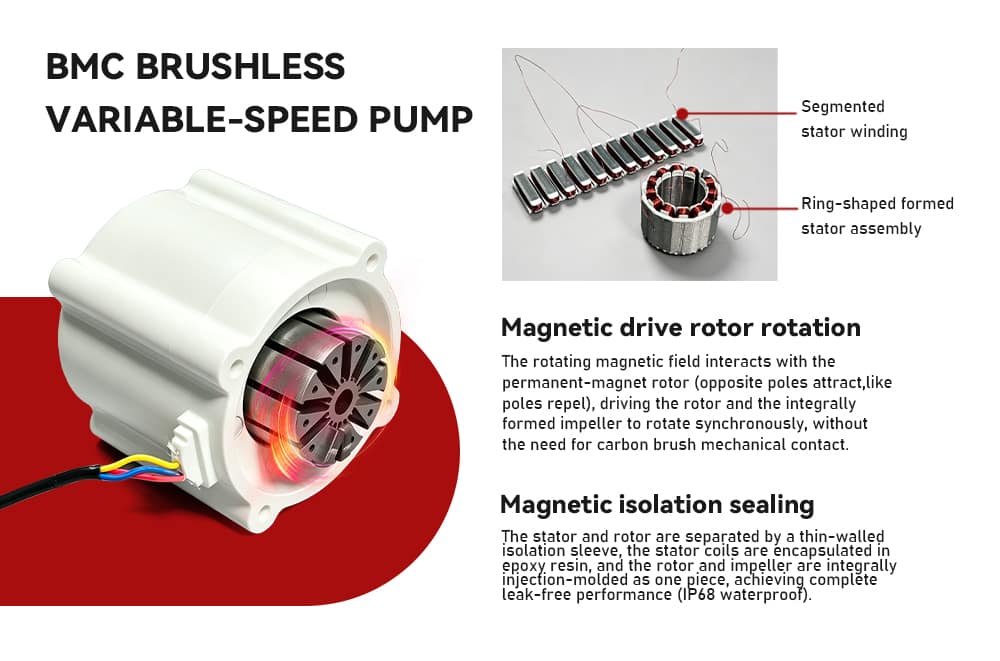
Magnetic drive
Opposite poles attract, like poles repel. The field turns the rotor and the integrally formed impeller together — no mechanical brush contact.
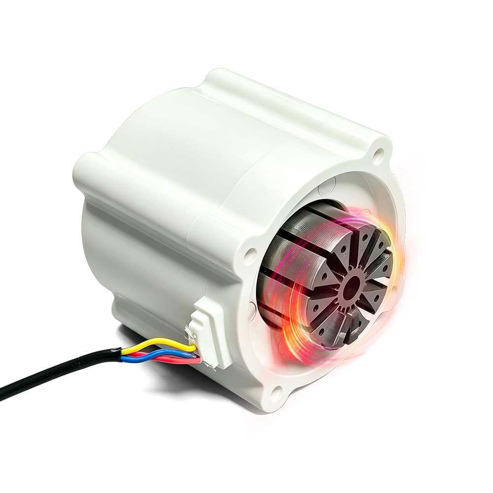
Inside the motor
Segmented windings become a ring stator, then a BMC shell. The rotor follows the field. There is no brush to arc, wear, or contaminate the cabinet.
01
Opposite poles attract, like poles repel. The field turns the rotor and the integrally formed impeller together — no mechanical brush contact.
02
A thin isolation sleeve separates stator and rotor. Coils sit in epoxy; rotor and impeller are molded as one. The motor side is specified leak-free to IP68.
03
Bulk Molding Compound encapsulates the stator core and windings as a single thermoset structure — rigidity, insulation, heat path and dampening in one shot.
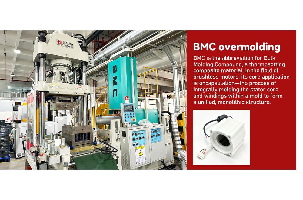
Coils are wound as segments, positioned and welded into a ring, optically inspected, then overmolded in BMC. The rotor is a permanent-magnet stack that follows the field. Because PEILI winds, forms and overmolds in the same plant, the motor is a controlled BOM rather than a bought-in can.
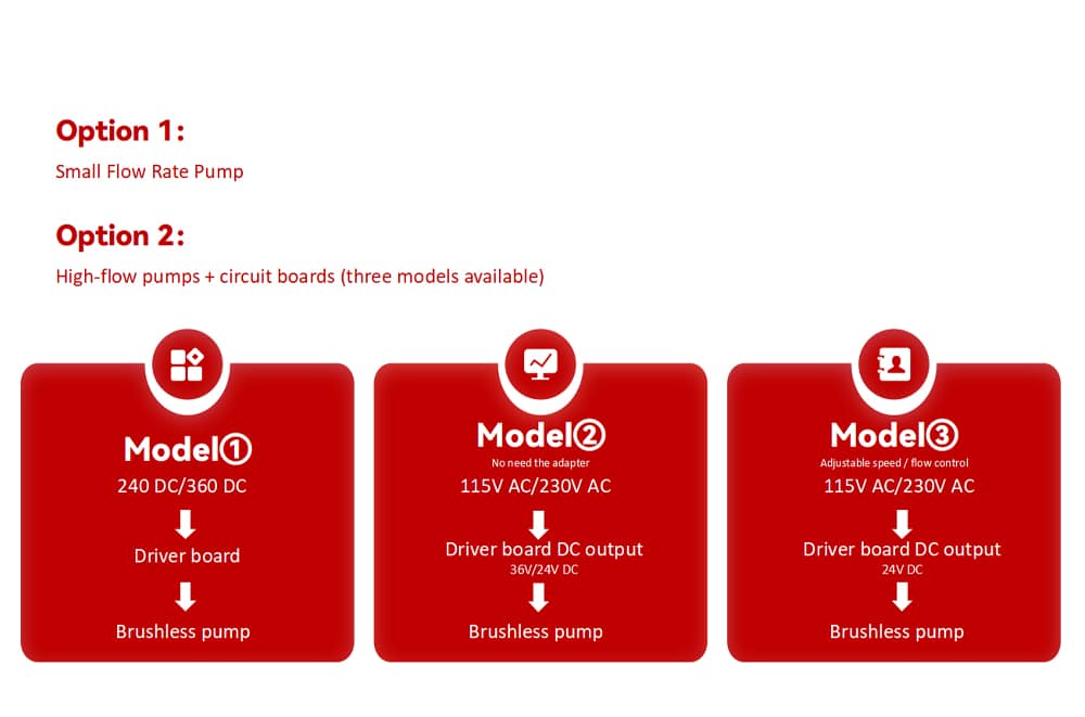
Driver
A rotating-field board takes mains or a DC bus, feeds the motor, and can hand 24/36 V to neighbouring loads. Speed is an external command when you specify Model 3.
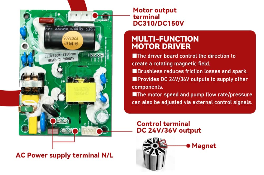
Model 1
For systems that already have a 24 V / 36 V DC rail.
Model 2
Mains in. Auxiliary 24/36 V for other components. No external adapter.
Model 3
External control signal sets motor speed, flow and pressure.
| Motor output | DC 310 V / DC 150 V |
|---|---|
| Mains terminal | N / L, AC 115–230 V kits |
| Auxiliary output | DC 24 V / 36 V |
| Control | Rotating-field drive, external speed command |